Mechanical fuel injection (MFI) was developed in the early days of automotive racing and is still in use today. MFI has a long history with many different formats of racing: drag racing, circle track racing, boat racing, and top-speed events like those held at Bonneville Speed Week. In fact, MFI pioneer Stuart Hilborn of Hilborn Fuel Injection became the first driver to ever eclipse the 150 mile-per-hour mark at El Mirage Dry Lake in April of 1948 using a self-designed constant-flow mechanical fuel injector.
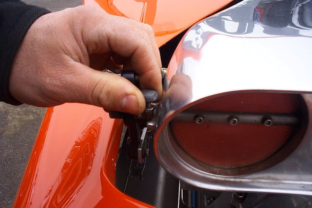
Making a simple adjustment of idle speed on Enderle racing mechanical fuel injection hat.
Mechanical fuel injection works well for naturally-aspirated or forced-induction engines and handles most any type of fuel — gas, ethanol blends, methanol, and even nitro blends. Setups can range from simple single-nozzle systems costing a few hundred dollars through to systems costing tens of thousands of dollars.
How does it work?
Once the system is primed, fuel is delivered directly to the engine for fast startup. It is simple to tune: there are only one or two adjustments to make in the bypass circuit for tuning a well-developed system, with air-to-fuel ratio as a powerful parameter to guide precise tuning. Finally, it is simple to set up – nothing more than a driver-controlled air valve for throttling with a simple hydraulic system to deliver the fuel.
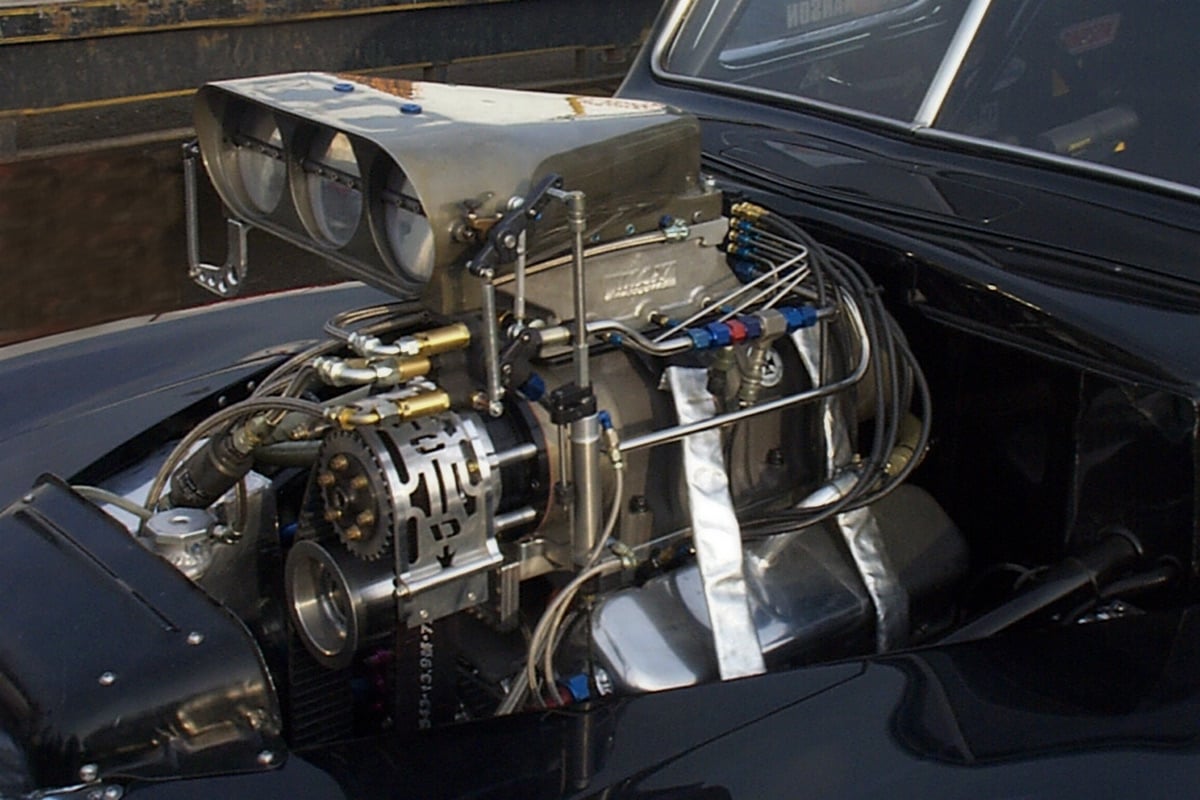
Racing mechanical fuel injection on an outrageous, supercharged nostalgia racing Ford sedan
Mechanical fuel injection works with a simple throttle-controlled air valve and a fuel pump, usually running at one-half engine speed. After pulling fuel from a vented fuel tank, the fuel is delivered through a barrel valve that controls the amount of fuel with the position of the air valve. Fuel goes through the barrel valve, then through fuel lines, directly to the intake system feeding each cylinder. For tuning, simple jetting changes control how much fuel enters each cylinder. On normally-aspirated engines, a properly set up mechanical fuel injection system provides instant throttle response, which makes the system great for racing applications.
Air is controlled with butterflies in a fuel injection hat or manifold. Usually, a mechanical cable with linkage connects from the driver-controlled throttle, and the butterflies are adjusted with a throttle stop for idle. Mechanical linkage connects the butterflies to the barrel valve. When the butterflies are opened, providing more air to the engine, the barrel valve is opened, providing more fuel to the engine.
This basic system is shown in the next illustration.
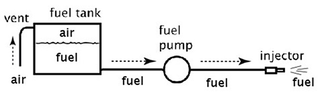
A simple fuel injection system starts with these basic components. Additional components are added for air and throttle control for power modulation. Additional injectors are added to provide fuel to each cylinder of a multi-cylinder engine with any number of cylinders, regardless of whether it is a two-cycle, four-cycle, or rotary engine configuration.
To compare, electronic fuel injection (EFI) works with a similar air valve although it may be throttle controlled or controlled electrically. An electric fuel pump provides the fuel at a constant fuel pressure. Electronic controls modulate the duty cycle of electronic fuel injection for the throttle position and other factors. While EFI has many more controllable features, at the same time, the cost and understanding of the technology for tuning is much greater.
Using different fuels
MFI systems with alcohol or nitro fuels, combined with forced induction can provide extremely high power levels. PSI screw-blown 500 cubic-inch V8 engines on methanol report power levels over 4,000 horsepower, and methanol has other benefits.
“It is our experience that alcohol’s performance is changed about half as much as gasoline with the typical changes in air conditions,” says Mike Chilando, owner of Alkydigger.
Don Jackson of Don Jackson Engineering, a former professional drag racing Top Fuel Crew Chief and engine builder and current Bonneville racer, reports power levels in excess of 10,000 horsepower from supercharged nitromethane engines with MFI. Those power levels were measured by Don’s special on-board dynamometer, installed on Connie Kalitta’s NHRA machines.
While methanol and nitromethane are common fuels, other fuels such as ethanol or race gas can also be used in mechanical fuel injection.

Illustration of mechanical fuel injection expanded with the addition of an idle control circuit, barrel valve, and multiple nozzles feeding a throttle valve hat assembly. These are used to modulate the air to the engine, common in racing around the world.
Components of a Mechanical Fuel Injection system
Constant flow fuel injection is engine-air-controlled with one or more of the following:
- Air scoop
- Ram tubes, often tuned length and tuned volume
- Plenum
- Ram manifold
- Throttle body or hat, to throttle the air.
Engine fuel supply i scontrolled with the following:
- Fuel tank to store the fuel
- Fuel tank vent allows air to get into the fuel tank
- Hoses or tubing to carry the fuel from one component to the other
- A mechanical fuel pump sized for the type of fuel, power level, and engine RPM range
- Injector hoses, distribution block, and injector lines to feed the injector nozzles
- Injector nozzles to inject the fuel into the air stream going into the engine.
Components of the fuel system
Understanding the basic layout of a fuel system, additional components make the mechanical fuel injection system useful.
- A barrel valve or metering valve controls the appropriate amount of fuel for starting, part-throttle, driving, and stopping. A barrel valve is also used to throttle the fuel for part-throttle driving. Most barrel valves have a very simple spool or metering cylinder inside of the valve for controlling the fuel flow. Linkage is added to operate the barrel valve spool or metering device from the air valve. This connection between the spool and air valve normally includes an adjustable turnbuckle.
- For starting and idle control, an idle circuit is normally provided to the system. For Sprint Cars, it is used as a secondary bypass at an elevated pressure for an increased surge of fuel as an accelerator pump out of the turns.

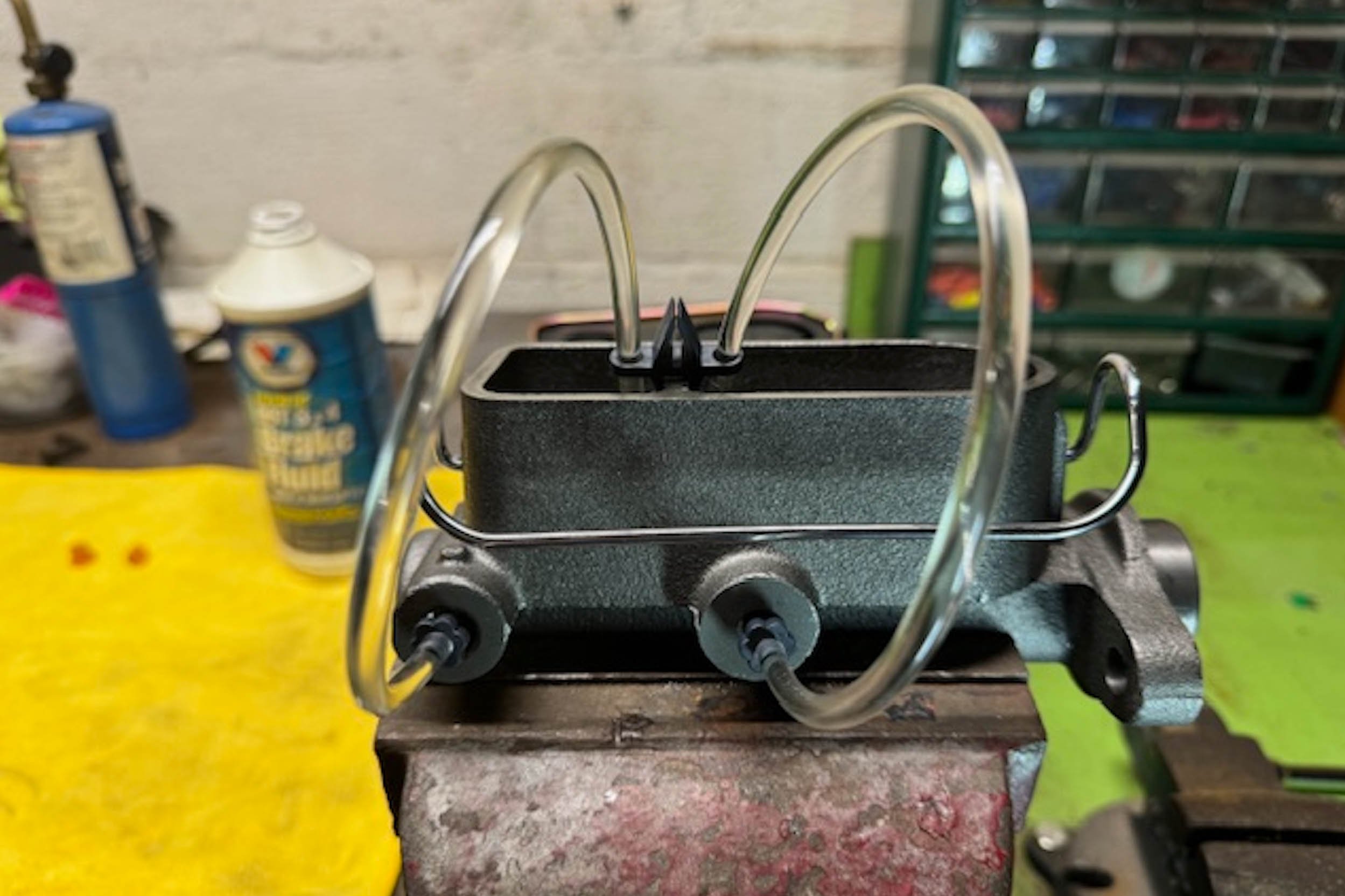
The barrel valve on this blown alcohol engine shown with additional fuel pathways for various drag race tuning functions: starting, burnout, staging, launch, and high speed lean-out.
In this system, idle air volume is set with a throttle stop. Spring pressure in the idle control valve sets the fuel volume as shown.
Some setups use two sets of nozzles. One set is for the throttle body or hat (if so equipped), and the other set is for the manifold ports. The second set is for controlling fuel distribution cylinder-to-cylinder. All engine nozzles comprise the fuel system jetting. Any bypass jets (including the main bypass, high-speed bypass, pump saver or others) divert excess fuel away from these engine nozzles to maintain a proper air to fuel ratio.
Most fuel injection systems have a main bypass circuit. For tuning purposes, this is a fuel return circuit, usually with a jet restrictor. In these setups, an oversized fuel pump delivers more fuel than the engine needs. Extra fuel goes back to the fuel supply through this main bypass circuit. A jet restricts the flow and controls the amount of fuel delivered to the engine. Changing the size of the main bypass jet is one way to tune a mechanical fuel injection setup, as a bigger jet leans the engine while a smaller jet richens the engine. Maintaining the air/fuel ratio by changing the main bypass is a simple method that leaves the rest of the engine nozzles untouched.
For an increased level of air/fuel ratio adjustment at higher engine speeds, an added high speed bypass jet brings more control.
Simple high-speed bypass circuit used for trimming the fuel curve in mechanical fuel injection.
Other components that are common in a mechanical fuel injection setup include:
- Fuel shut-off valve
- In-line fuel filters
- Pressure gauges or transducers for data recording
- Air filter on some installations such as those used in dirt track racing or on street-going vehicles.
If you would like to learn more about tuning your setup, check out our earlier article on the effects of weather on mechanical fuel injection.
Extra nozzles
Once the basic setup is established, extra nozzles can be added to further enhance your engine’s performance. Some MFI setups add idle dribblers for better control of the idle fuel amount delivered to each cylinder. This is especially common in racers with tilted engine installations such as dragsters and funny cars with engines often tilted down. Some boat engines are tilted down or up to line up with the propeller drives that benefit from extra nozzles in the ports to control fuel distribution.
Extra nozzles can be added for more fuel at the high end for ram air effects. For example, in Top Fuel racing, it is common to use several extra sets of nozzles in a setup. A typical installation would include:
- Hat nozzle – one set
- Blower lubers – partial set, commonly in the rear of the blower
- Manifold nozzle – two sets
- Cylinder head port nozzle – two sets
MFI fuel bypass jets control the fuel mixture to the engine. These jets divert a certain amount of fuel away from the engine and back to the fuel tank, which is useful for controlling the overall fuel flow to the engine. Additionally, high-speed bypass jets come on when the engine reaches a certain engine speed. This decreases fuel to the engine in higher engine RPM levels where the volumetric efficiency may fall off, reducing the amount of air demand per revolution.

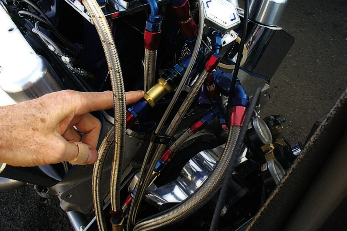
Nostalgia nitro dragster engine shown with hat and port nozzle distribution blocks and lines. Port nozzles are often put on a pressure poppet (brass poppet lower right of center photo) that holds them closed until engine speed increases. This provides more fuel pressure at low engine RPM for good response.
Although most racers use trial-and-error to set up their fuel system’s jetting, maintaining numerical control of the setup can provide consistency and maximum power. Finding and maintaining the optimum air/fuel ratio for your setup is the simplest way to determine bypass jetting values for optimum tuning.
External Support Systems
Understanding fuel injection isn’t complete without understanding how other parts of the setup work with the fuel injection.
A strong advantage of MFI is its adaptability to different cylinder configurations. For most any configuration–such as inline, V-style, opposing, or rotary engines–mechanical fuel injection can be easily adapted to the various different cylinder locations. Considerations include low manufacturing cost and ease of subsequent maintenance.
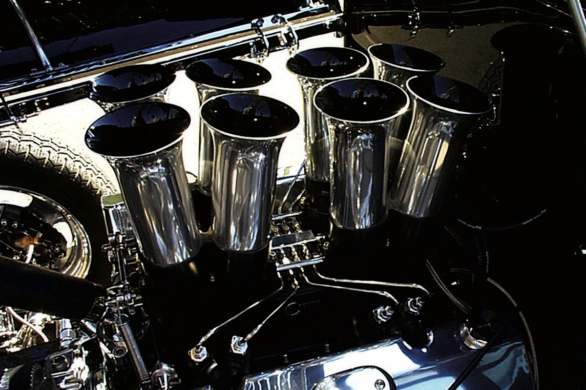
Mechanical fuel injection, with stacks, on a V8 street rod engine. The open, flared inlets smooth the intake airflow for more horsepower.
Fuel pump size is important. Normal installations involve a fuel pump about 25- to 50-percent larger than the engine demand. Tuning is simple by controlling the amount of excess fuel bypass back to the fuel supply. In addition, the fuel pump should be fed with an adequate supply line to avoid inlet cavitation.
Some racing classes such as drag racing’s Nostalgia Top Fuel restrict the size of the fuel pump. To meet the class requirement, racers use oversize fuel pumps with inlet restrictions. That is providing extra fuel for more power benefits at lower engine speeds and a whole new era of tuning tricks. For example, in Nostalgia A-Fuel drag racing, class rules in the USA specify a fuel pump of approximately 12 GPM. The latest trick is to use a larger fuel pump that would flow approximately 15 GPM without any restrictor. An inlet restrictor limits the fuel pump output back to the 12 GPM value. Because this rating is made at a specific fuel pressure and fuel pump speed, the 12 GPM value is sustained at lower pump speeds. For nitro racing, that provides extra power at low engine-RPM from all of the oxygen in the nitro fuel mixture.
When considering any tubing running fuel between the fuel pump and the engine, avoid right angle fittings or other sharp curves. They cause flow problems which in turn creates poor consistency and power when the engine is under load. Hose ends with tubular bends should be used instead to avoid flow problems.
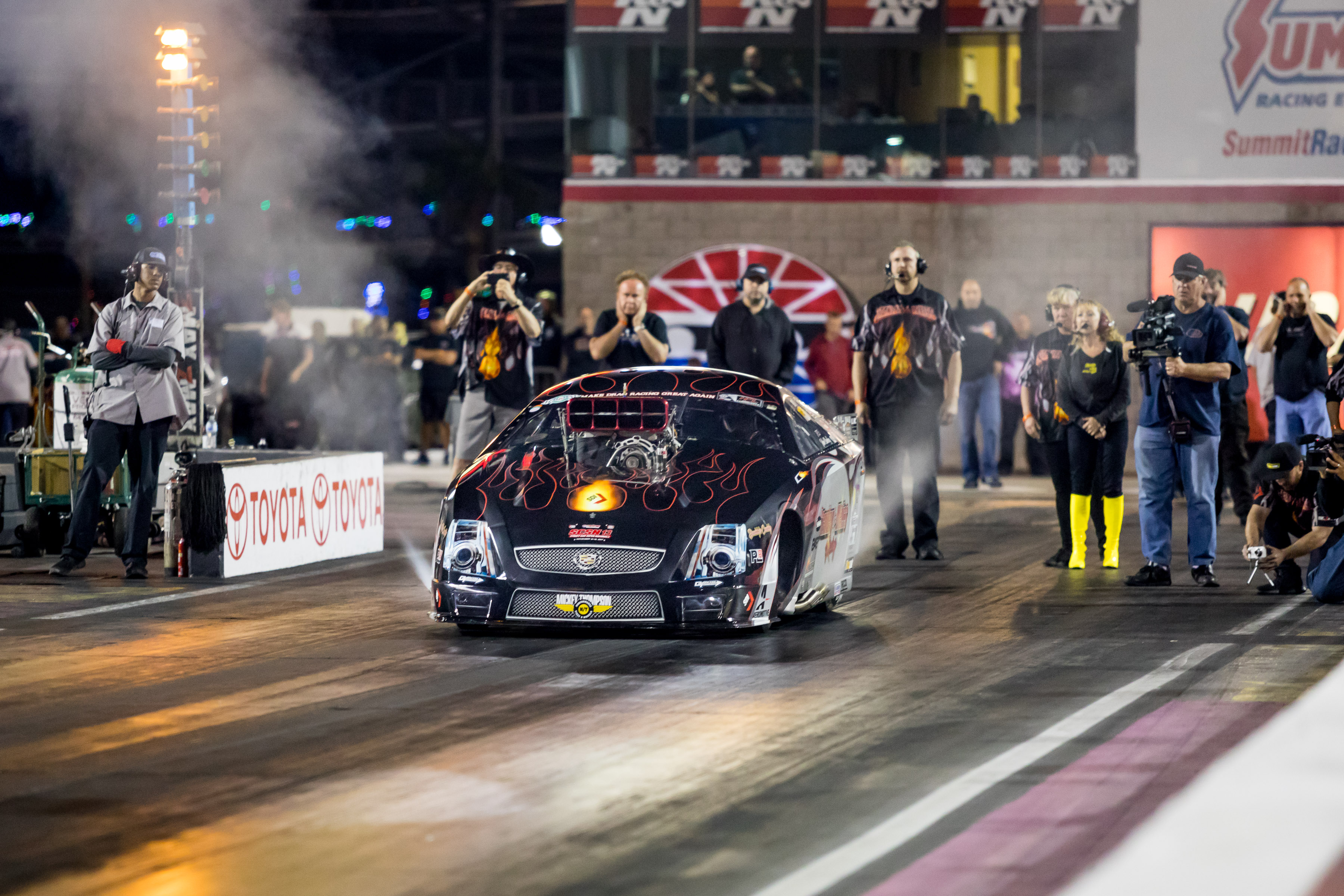
The world’s fastest supercharged doorslammer–Camp and John Stanley’s “Daddy’s Caddy”–runs a mechanical fuel injection system from Rage Fuel Systems.
Conclusion
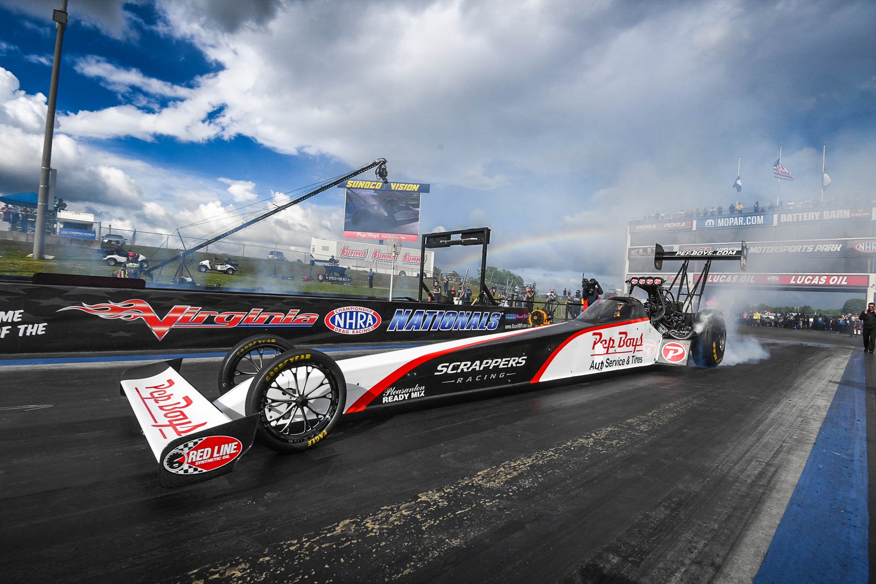
Mechanical fuel injection is easily configurable from small setups to very large power outputs. Small 4-cylinder engines making 100 horsepower are easy to do in midget racing. On the other end of the spectrum, MFI is a staple of the huge 10,000-plus horsepower engines in NHRA’s Top Fuel and Funny Car applications.
Racers with a little bit of MFI knowledge regularly exceed extended performance goals. Mechanical fuel injection is a low-cost, powerful fuel system that wins!