 Geometry class may not have been the highlight of everyone’s high school experience. The view out the window usually won out over chalkboard equations involving angles and volume.
But when it comes to building a high-revving engine with eight cylinders screaming in harmony, geometry rules.
Valvetrain geometry, that is.
Geometry as applied to the engine compartment, of course, is a bit different from those dry classroom lessons. To start at the beginning, “valvetrain geometry” in an overhead-valve engine refers to the job of ensuring the valves, pushrods, rocker arms, lifters and camshaft are all aligned and rolling together with maximum efficiency. Of particular interest is the arc generated by the motion of the rocker arm.
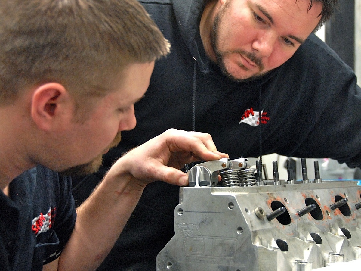
Analyzing and correcting valvetrain geometry is an important part of the teachings at the School for Automotive Machinists.
If turning 9,000 or 10,000 rpm, having a solid valvetrain is absolutely necessary.–Shawn Hooper, SAM Racing

As a practical matter for performance engines, this means determining the correct pushrod length, the rocker-tip sweep across the valve and the rocker arm/pushrod locations, among other considerations. You want the straightest path for all the components, but not if it means running a pushrod through the middle of a port.
Valvetrain geometry is a critical lesson in the curriculum at the School of Automotive Machinists in Houston where cylinder head specialist Shawn Hooper and SAM’s director of education, Judson Massingill, offered their expert advice to EngineLabs. As with every other aspect of engine building, you need to approach the valvetrain with a plan, rather than a reaction.
First consideration when building heads
“Valvetrain is definitely one of the first things we’re going to consider when we’re going to do a set of heads,” stresses Hooper. “What kind of valvetrain and what kind of rpm are we working with, and obviously cam profiles.” Common modifications during a build such as having the block or heads decked, or installing a cam with a different-size base circle, will alter the valvetrain geometry from the previous configuration, so must be taken into account.

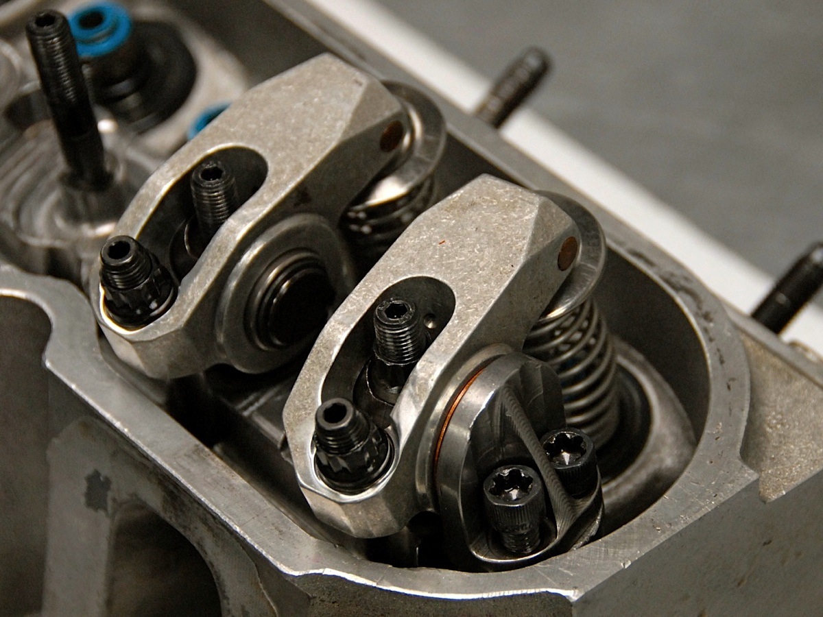
Sometimes the rocker must be twisted around to get the proper geometry, but there are space limitations that require custom solutions. LS motors, compared to big-blocks or even small-blocks, have a real narrow valve cover rail. This base was milled down, and a ‘kick-out’ valve cover was fabricated.
Get the valvetrain geometry wrong, and instead of components seating nicely, they’re smashing into the valve seat, then all other parts receive the shockwave, possibly leading to breakage.
“That’s why when you hit valve float, its sounds like a rev limiter,” says Hooper. “Because basically all those parts are not opening anymore. There are gaps between them. Everything is trying to do its own thing, and it doesn’t work.”
For most mild street builds and weekend bracket racers, valvetrain geometry doesn’t deviate too far from stock. Decades of tried-and-true speed strategies have resulted in reliable formulas. A budget performance build generally doesn’t require an expensive custom valvetrain and can rely on off-the-shelf matched parts.
That doesn’t mean, however, you can just blindly bolt on all the pieces and hope for the best.
“There is no ‘cam and kit.’ You can start looking at that, but you must verify,” says Massingill. “Some of them are too generic.”
Certainly an engine builder can start with the cam and kit offered by any reputable manufacturer—they often work just fine, but for a quality build the cam needs to be degreed and the valevtrain settings verified. Perhaps the most critical measurement during preassembly with regards to valvetrain geometry is the “sweep” of the rocker arm across the top of the valve.
“The simplest way to check it is to mock it all up on the motor, and just check how far does that rocker arm sweeps back and forth,” says Hooper. “We really don’t want that rocker arm to be traveling far across the valve and coming back. Every rocker arm is going to cause an arc. Obviously we have a radius from the center to the tip, and that doesn’t matter what kind of rocker it is. If it’s a pedestal or a stud mount, it’s going to make some kind of arc. And the longer the rocker arm is, basically the wider the arc.


The Sharpie method is a useful bench test to determine if you have the correct rocker arm sweep across the top of the valve. As you turn the engine over and put the valvetrain through its motions, the tip of the rocker will leave a mark to show where contact occurs. Ideally, you want a narrow sweep, more or less centered, rather than a fat sweep or one that looks like it's about to fall off the edge.
“We don’t want it to where instead of opening the valve, it’s making more of its movement across the valve itself,” adds Hooper. “If the rocker is wasting motion moving across the valve instead of pushing it straight down, you can actually lose lift.”
A tried and true method of checking sweep is to set up the rocker arm, get a checking pushrod, adjust it down, and mark the top of the valve with a Sharpie. Then turn the motor over and see how wide an area is cleaned up. Ideally, a narrow band should be wiped clean from the Sharpie mark, and it should be mostly centered (see photos).
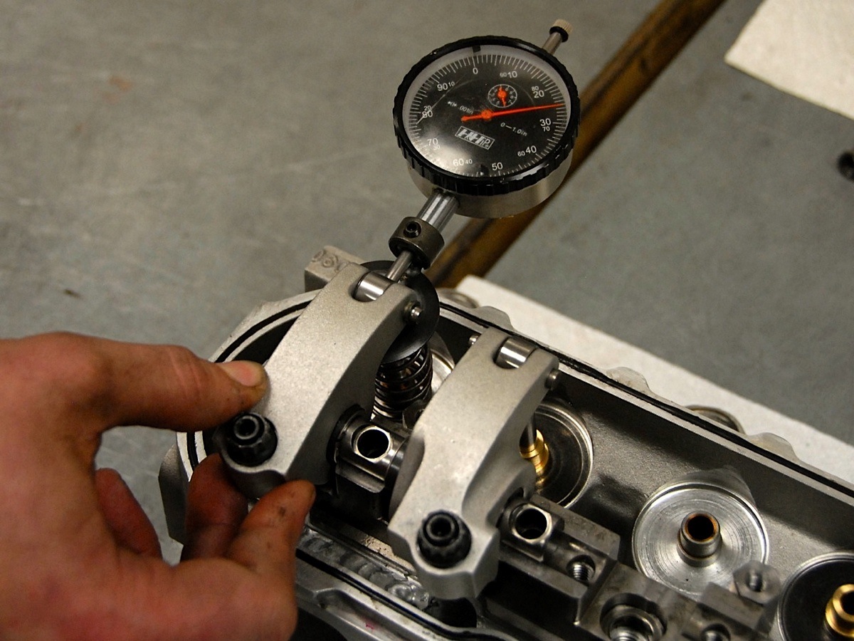
A readily-available valvetrain geometry tool like this will measure the amount of sideway travel over the valve tip. You can observe the rocker breaking over.
According to Massingill, it’s better to have a narrower sweep that’s a little off-center (most of the time to the exhaust side) than a wider sweep, even if it’s perfectly centered. The width of the sweep is a little more important than the location. If you’re getting a narrow sweep, the side loads on the valve stem are reduced as compared with a wide sweep.
Once you’ve got the fundamental geometry correct, there are other efficiencies you can seek out.
“If I can get my valvetrain smooth and not have any issues with the harmonics, I can start taking away some of my spring pressure,” explains Hooper. “Instead of having to force it, to put more pressure to keep it under control, now my valvetrain is under a lot more control by itself so I can start taking away spring pressure. That’s going to free up friction and that’s going to free up power. That’s what we ultimately want to do, to make it as efficient as possible.”
Valve spring considerations
It’s easy for the casual racer to get his head turned by the parts that the fastest guys use, but you can get fine valvetrain performance on a budget.
“If turning 9,000 or 10,000 rpm, having a solid valvetrain is absolutely necessary,” warns Hooper. “With a little street motor, there’s really no need for any of that. Having a good geometry is still a major plus. But not having killer rockers—Jesels and all that—yeah, it’s a nice investment and you’re never going to have to worry about anything breaking. But do you really need it? No.”
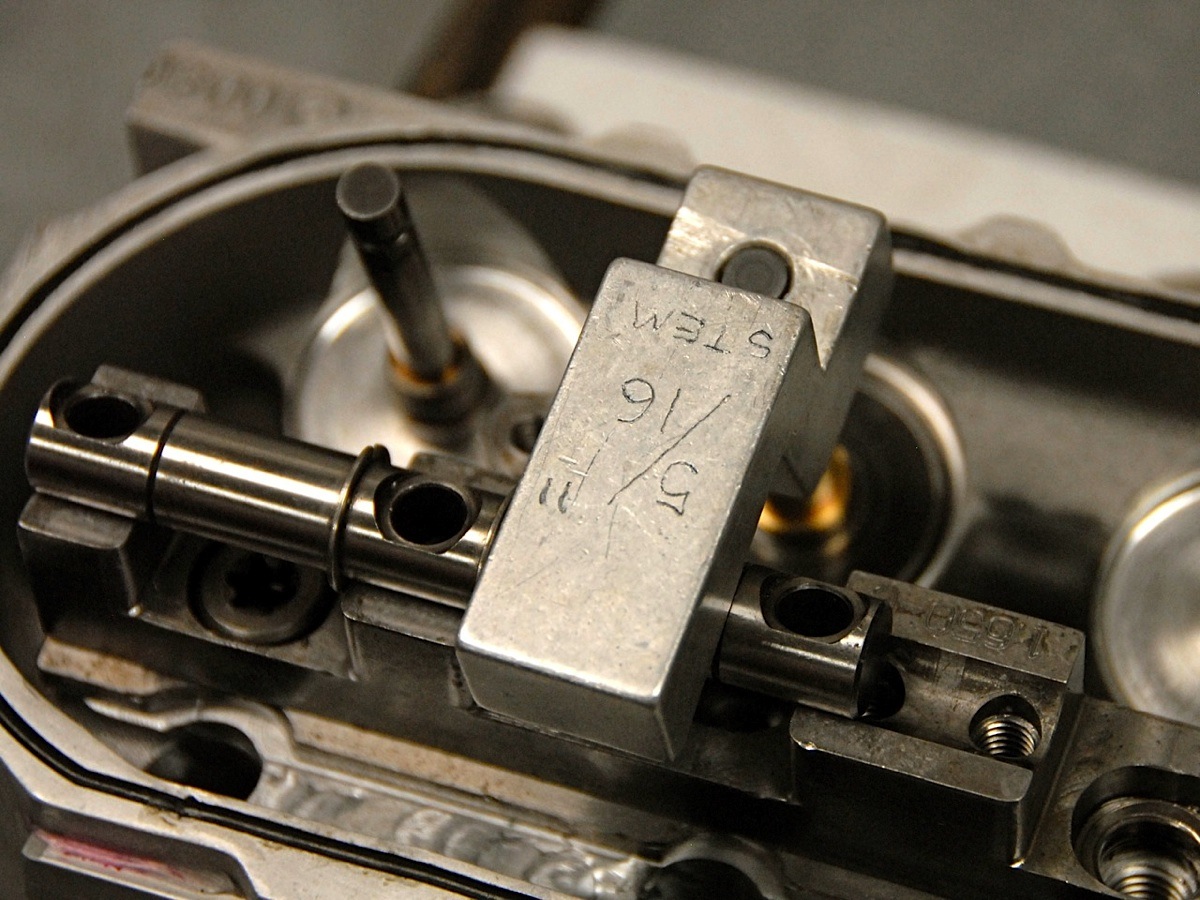
This Jesel tool is used to set the stand height on their rocker systems, and can speed geometry calculations along. When this tool is set on the stand, if the tip of the valve is pretty much flush with the top of the hole, it’s right. If the valves is on the short side, shim is taken out. Taller valves require additional shim.
That goes for valve springs as well.
“If they’re not turning over 7,000 rpm, there’s no reason in the world to run an old double-spring set-up, an inner and an outer with a dampener, and all that,” says Massingill. “Over-springing with an old-style dual-spring is the biggest mistake a lot of people make. The beehive springs we have today will turn 7,000 to 7,500 until the world freezes over.”
Obviously, racers reach a point where off-the-shelf strategies no longer yield results, and the valvetrain geometry calculus takes on new dimensions.

An adjustable pushrod is an indispensable tool for determining the correct pushrod length, and to check and change the sweep of the rocker arm.
“We have a few things we have to look at with rocker arms themselves,” says Hooper. “We’ve obviously got a rocker arm ratio—the amount the cam lifts it, it’s going to lift the valve so much. But we’ve also have what we call pivot length to the actual rocker arm, and that becomes very critical when we get into high-rpm motors because of that arc that it creates. The wider the pivot length becomes, the larger that arc will be. The shorter it is, that’s going to make a real tight arc.
“When we get into these race engines, where we’ve got a bunch of lift, that’s where we want to start to get longer pivot lengths,” he continues. “But with a lot of these cylinder heads, we’re real restricted with that because obviously if I’ve got a pushrod sticking half-way out the intake flange, that’s not going to work very well.”
One solution available with a Jesel-type set-up is to “twist” a rocker in relation to the others to get the optimum angle for the pushrod and rocker arm.
Here’s a head that SAM Racing used in the most recent Engine Master’s competition. Rules require a stock-style rocker system. The head had no pushrod holes as delivered, giving SAM Racing flexibility in locating the rockers as well as the ports. SAM kept the pedestal-type rocker but with a ‘twist.’ Moving the rocker in such a fashion created its own challenges as there is more force on the rocker. So SAM developed a unique trunion.

Class Time
Students at the School of Automotive Machinists have access to a full curriculum of engine-building subjects. The Engine Block class alone is a nine-month course, and students can expect to spend about two weeks in a deep dive just on the subject of rings.The other major classes at SAM include a Cylinder Head course and a CNC course. SAM offers a curriculum focused like a laser on building racing engines, and the school’s graduates can be found in the garages of the top racing teams in NASCAR, NHRA and the IRL.
“What we can do, instead of using one single shaft that goes across, we’re going to have two different rockers here. What that does too, instead of having to have a bunch of offset, I’ll just twist this rocker off to the side,” adds Hooper. “For one thing, it makes it so I can put a much longer pivot length to it. It also makes it so I can have a nice straight rocker. Whenever we put a real offset where this adjuster is offset in the rocker, it gives the rocker a lot of twisting motion and adds a lot of weight to the rocker. So if we can get away from that it definitely helps a lot.”
Recent Developments
Although the fundamentals of valvetrain geometry haven’t changed in recent years, what has changed are the tools and materials available for precision tuning.
For example, the arrival of 3D digitizers and 3D printers has allowed engine builders to quickly conceptualize and test valvetrain parts in ways that would have seemed miraculous to earlier generations. With a 3D printer, a plastic pedestal mount, for example, can be conjured up in short order for test purposed, where previously this kind of custom parts experimentation would have taken lengthy back-and-forth with a machine shop.


Modern computer design and simulation tools allow engine builders to analyze and locate valvetrain components with exact precision.
“The geometry really hasn’t changed much, we just now can machine anything we want, and put the valve where it needs to be in the head, and then we can move the rocker arms to fit that with these stands—up or down, back and forth, to get the geometry,” Massingill says, adding that materials technology has also changed the valvetrain calculus and gives a early credit to PSI for revolutionizing the production of valve springs. “The big thing, I have to say, is valve spring material. We just didn’t really have high-quality springs until 15 years ago or so. The first thing the founder of PSI really did that made a difference—he certainly understood harmonics and that stuff—was determining that what was breaking the springs was impurities in the wire. It was literally that simple. To my knowledge, in the U.S., he brought this to the front.”
With the improved quality of spring manufacturing in the U.S and Japan, and the adoption of “beehive” springs, old methods have fallen by the wayside. For years, the racers’ solution to broken springs was usually to make the springs bigger, or use an inner and outer spring together.
“I hate to use the word ‘crutch,’ but that’s what it was,” Massingill says.
Critical spring technology
The problem with those chunky springs combinations was that so much of the energy in the spring was used to keep itself from moving. With the better, stronger spring materials now, racers can ran smaller springs, diameter wise, with smaller coils, with the same spring pressure. It’s a significant weight savings on the valvetrain.
“With the quality of the springs we have today and the good ramps they’ve come up with on the cams, we’re in pretty good shape,” Massingill confirms.


Computer software can not only digitize a cylinder head but also mock it up on the block to help determine proper geometry.
Recent gains in manufacturing quality have also given new life to older materials. Titanium was the money metal inside the engine. Now steel retainers are making a big comeback. Tool steel retainers are increasingly found in high-end race engines because they can be made thinner than titanium, with the same strength and same weight.
The quest for ever-lighter valvetrain pieces yields results, but there are limits. Pushrods, for instance, have gone the other direction. Racers have learned the hard way over the years that, in high rpm applications, the pushrods were actually “pole-vaulting” or flexing, at high rpm. Upon teardown, however, the pushrods weren’t bent, so all was assumed to be working fine. But with pushrods flexing under stress, the actual valve timing wasn’t anywhere near what the cam profile was designed to actuate.
“Now we have these huge pushrods,” says Massingill. “We used to worry about the weight. But now we don’t worry about the weight. Make that pushrod where it stays stiff and then the valvetrain will stay stable at a much higher rpm.”

Proper valvetrain geometry in a race engine reduces harmonics and may allow the builder to back off on spring pressures.
Sometimes, despite recent advances, the old ways actually do work best.
“[In high-end drag motors] We’ve gone back to what Ford did in the early 1960s with their old FE engines,” Massingill recalls. “We’re running pushrods today, like in our big motors in our Mustang and the orange Camaro, the cup is back in the pushrod, and the ball is in the adjuster in the rocker.”
We think the Total Performance engineers of the ’60s would get a kick out of that.


