
 Everyone knows that cold air makes power, and in a boosted application the intake air temperature becomes even more critical as heat climbs on the way down the track. A quality intercooling system is a must, and since the advent of the in-car air-to-water intercooler design, racers have been looking for that extra edge over the competition in system design and performance.

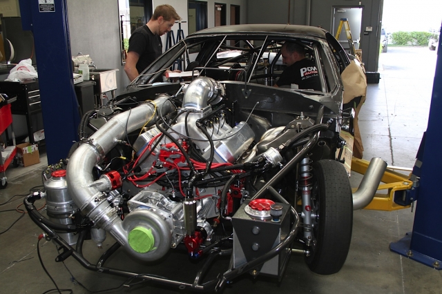
Project BlownZ on the jig at Phil Mandella Race Cars
In the interest of improving performance from the ProCharger F-1X supercharged LSX engine in Project BlownZ, we’ve decided to completely revamp the induction path from the supercharger to the inlet elbow atop the intake manifold using a new custom air-to-water intercooler from Chiseled Performance and tubing and other necessary fabrication items from the team at Race Part Solutions.
The application to be covered in this article references supercharging, although the same concepts can be applied to a turbocharged package in most cases.
The Why

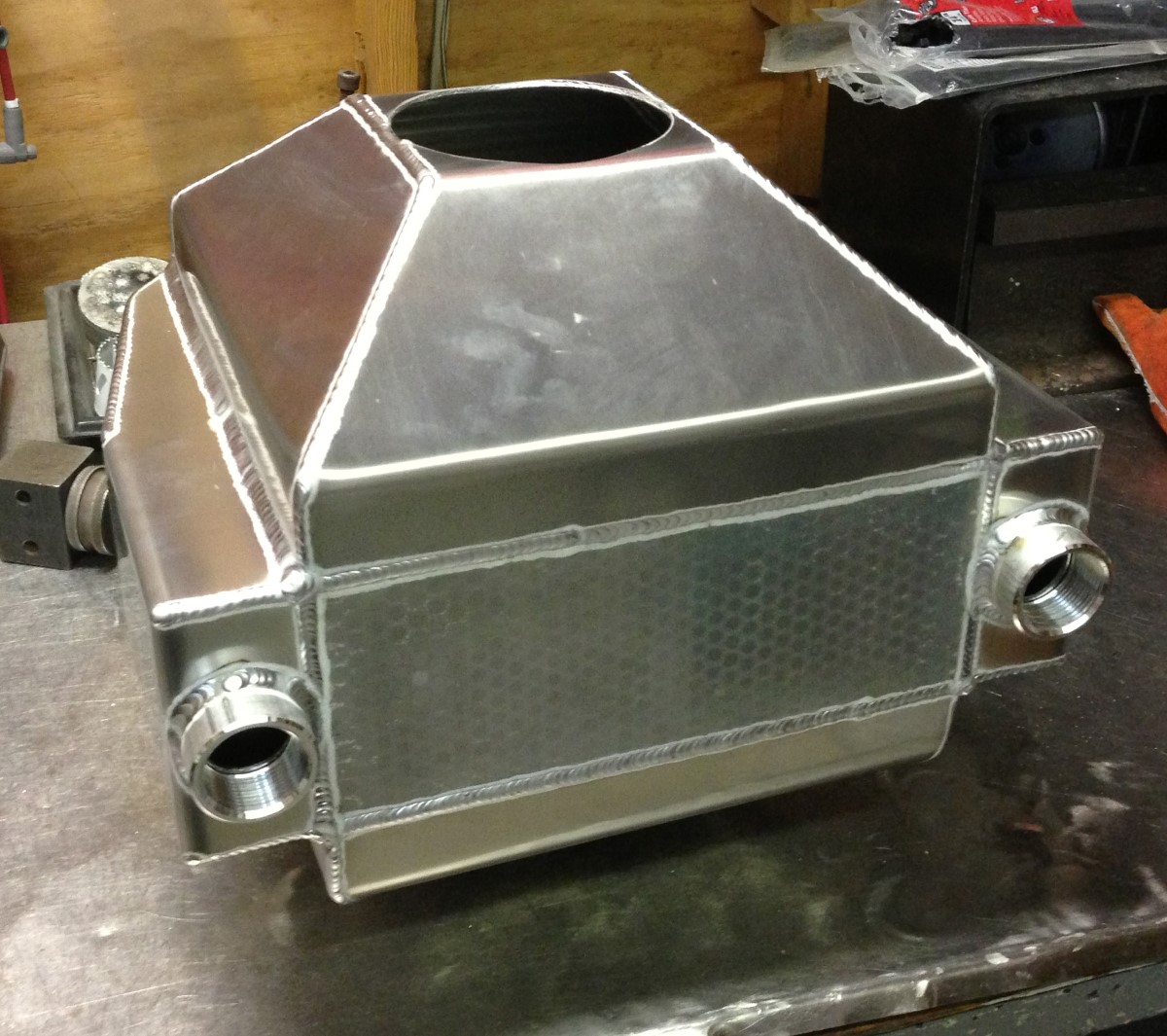
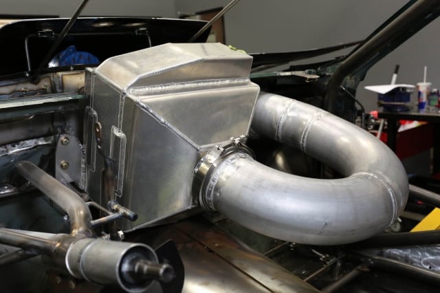
Our custom IC3000 intercooler from Chiseled Performance uses a straight-through design to minimize pressure drop across the core as the air flows through the cooler.
The purpose of an intercooler in an all-out racing application is to remove the heat in the air charge that a turbo or supercharger introduces during the compression process. There are a number of advantages to using an intercooler. Most importantly, reducing the heat in the air charge increases the air density, which improves the potential for power production. In addition, the reduction of heat decreases the tendency of the engine to knock during the combustion process.
There are two basic styles of intercoolers – air-to-air, and air-to-water. An air-to-air cooler uses ambient air flowing over the cooler’s core to drop the inlet charge temperature, and is often used in a street application like ProCharger’s P-1SC or i-1 supercharger systems. It has the advantage of simplicity and good efficiency with less heat soak over long periods of time.
An air-to-water system uses a primary heat exchanger that uses a liquid coolant to carry away heat from the intake air, and in street systems that coolant then goes through a second heat exchanger that is cooled back down by ambient air. Because it offers more flexibility in under-hood packaging, you’ll see it in factory roots-style supercharging systems like those found on the Shelby GT500, Cadillac CTS-V, and Corvette ZR1.
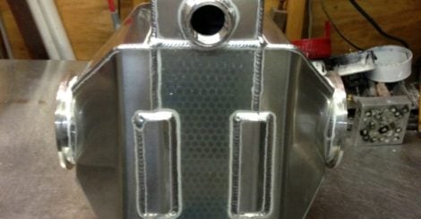
Left - Chiseled Performance can build whatever style of intercooler your application requires - ours sandwiches the core with V-band connections on both inlet and outlet. Right - This is an air tank for the standard IC3000. In this photo the center hole and V-band is yet to be installed.
An air-to-water design in a racing application uses a large, separate water tank that constantly feeds a stream of ice-cold water through the plumbing and the intercooler core to provide a very substantial drop in temperatures across the cooler face, and this is the type of system we have in BlownZ. For dedicated drag racing, where possible and allowed by the rules, an air-to-water intercooler design is most efficient to reduce charge air temperatures and boost ultimate horsepower potential. When designed properly, the ice used in the cooler tank will help to provide charge air temperatures that are actually lower than the ambient air temperature – something that’s not possible with an air-to-air intercooler.
Our application called for 1-inch female NPT fittings for the water connection, but Chiseled Performance can build them with male -20 A/N fittings as well.
Efficiency of the intercooler is of the utmost importance, and that’s where guys like Robert Rojas of Chiseled Performance come into the equation. The other important factor to note is the flow restriction presented by the use of the cooler and attendant tubing required to duct the air from the charger to the intake manifold. Chiseled Performance has been building intercooler systems for many heads-up racers for years, and Rojas is well-versed in providing the proper product for the application.
The What
With Robert’s input taken into account, along with some ideas that we had internally and through discussions with Keith Wilson of Wilson Manifolds, the decision was made to use a cooler design that is very different from some of the ones commonly seen in race cars today.
The large bends in the tubing really help to keep the air flowing more smoothly. – Robert Rojas, Chiseled Performance

As you’ll notice from the photos in this article, our cooler sits just behind the windshield, as close to the intake manifold as is possible for a number of reasons. The intercooler, as a function of its design, aligns and diffuses the airflow after any turbulence created by bends in the inlet tubing, and by having the intercooler in the closest possible position to the intake manifold, we’ll get the straightest, most equal airflow to all sections of the manifold itself.
The closer the intercooler is to the engine, the more dense the air charge will be – that’s why those OE water-cooled applications we mentioned above have their intercoolers inside the intake manifold, just prior to the entry to the cylinder head. Since that’s not practical for our application, we placed the cooler as close to the intake manifold as possible, and removed as many bends as possible prior to the throttle body to maximize the airflow and cooler efficiency.
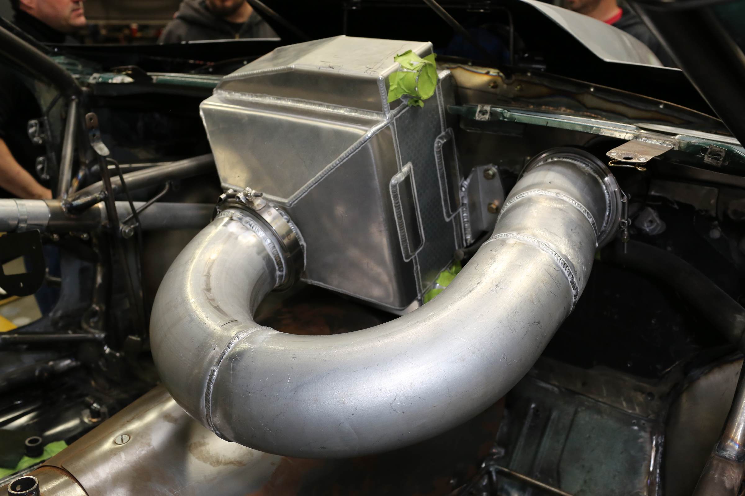
We used a very gradual bend radius to turn the air entering from the engine compartment into the intercooler to lessen pressure drop.
In addition, making the airflow do a U-turn inside the intercooler with the use of sheetmetal end tanks is a crude way to bend the air, and it loses efficiency in the process. By presenting a straight shot for the air through the intercooler, and doing all the turning via large-diameter, large radius bends, we can keep boost up and temperatures down. Rojas explains, “There is pressure drop in the tubing, especially if its a long run and has a lot of bends in the system. The large bends in the tubing really help to keep the air flowing more smoothly, and also helps in temperature reduction since the air is not cramming up in the bends, which will create heat.”
For our application, Rojas created a custom version of his 3000-horsepower air-to-water cooler. “The air flows straight through the core instead of having to curve into the core at a 90 degree angle. We also used 5-inch V-bands instead of the typical 4-inch design. This is the best flowing design, but it is very hard to package in most cars, especially with the 5-inch tubing,” he says.
There are lots of options when it comes to ordering an intercooler like ours from Chiseled Performance such as which V-band connections on the inlet and outlet, female NPT fittings or -20AN fittings for the water connections, and what type of air tanks the racer wants for their particular layout – the standard forward-facing air tanks, opposite-facing air tanks, or even the straight-through design like we have.

Left - Chiseled's standard IC3000 design uses an air tank on each side of the core like ours does, but the inlets both face the same direction rather than a straight-through design. Right - The massive core of the IC3000 along with the V-band inlet and outlet, and the female NPT fittings.
In addition, a remote water tank is required for an installation like this, and Chiseled Performance offers either their standard 5-gallon tank with a Rule 3700 in-tank pump to process the water/ice mixture, or a custom tank if you have specific size limitations. Rojas specializes in building intercoolers for hard-to-fit applications. If you can provide a rough drawing of what you’re looking for, he can help you refine it into a finished product.
BlownZ Winter Upgrades
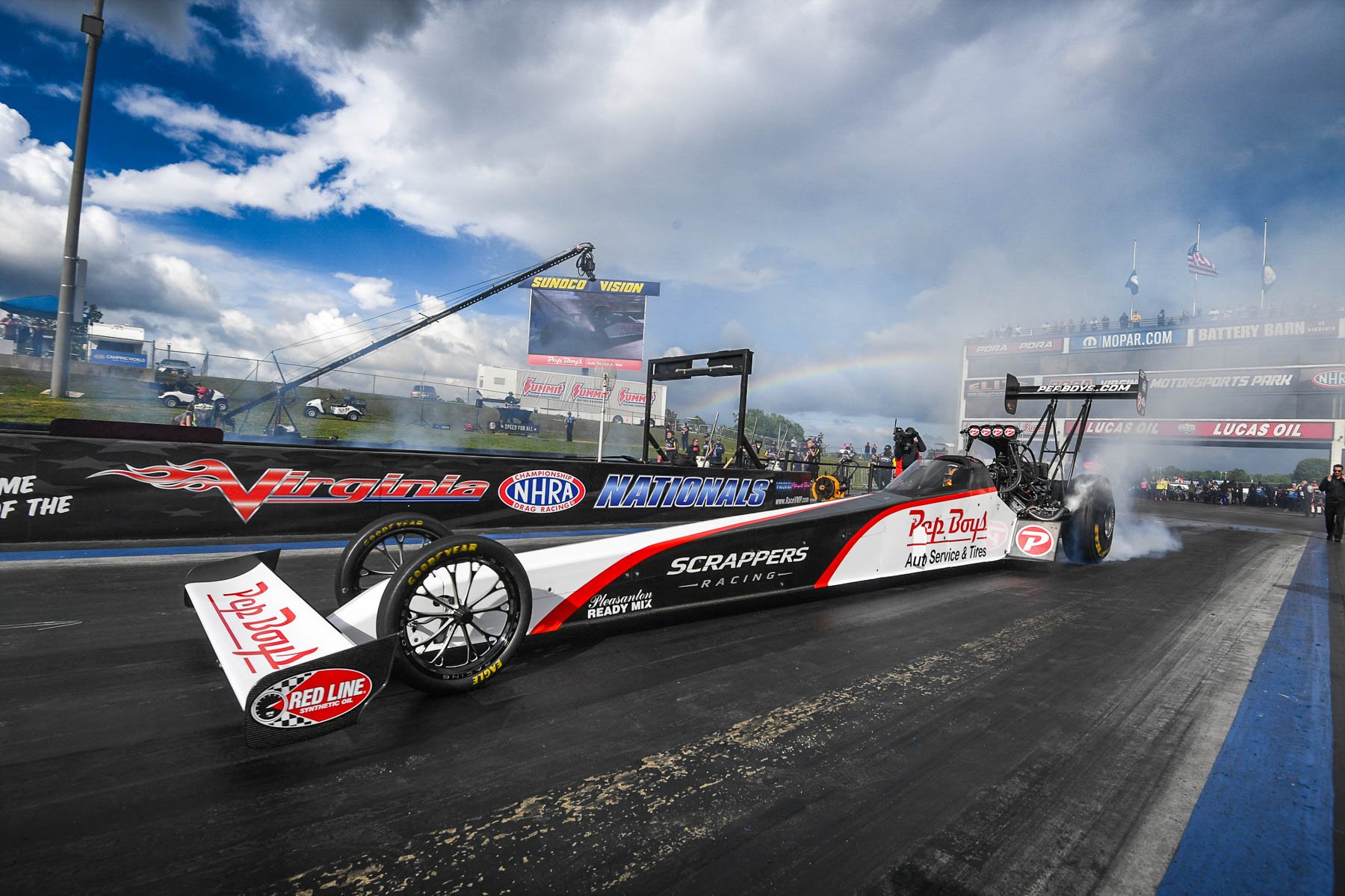
Project BlownZ is Power Automedia’s in-house “shop car” that races in the NMCA West‘s Street Outlaw, PSCA‘s Wild Street, and WCHRA‘s 275 vs. 28×10.5 drag racing classes. The car competes on a 275-wide drag radial in these classes, where every ounce of performance is sucked out of the engine and applied to the ground.
Over the 2013-14 winter, we’ve completely updated the car with a brand-new 25.3 chassis from Phil Mandella Racecars, a new 400-cube engine from the LS wizards at Late Model Engines, new rear suspension parts including a Pro Series 46-inch torque arm and control arms from Racecraft among other off-season modifications.
When the car is complete in the upcoming weeks, it will be a state-of-the-art machine with all of the industry’s latest tricks and tools applied in an effort to get it to the front of the pack. You can see more of BlownZ’s upgrades by clicking here.
It’s In The Tubing
The 5-inch tubing referenced above by Rojas can only mean one thing – as with much of our project, we’re departing from the norm to try something different in an effort to gain an edge over the competition. As BlownZ will be a basically brand-new car for the 2014 season, we weren’t constrained by previous modifications and were free to try something new with the 5-inch inlet tubing, to minimize restriction and maximize performance.
The 5-inch tube came to us thanks to the team at Race Part Solutions, where Robert Stevenson assisted us through the process of building our new system. He explains, “Over a length of intake tubing, friction causes restriction to airflow and imparts additional heat into the intake air charge. A short 3.5-inch orifice exiting the ProCharger benefits from transitioning to larger tubing to minimize frictional losses and reduce any additional heat imparted into the air charge.”
“Longer runs of tubing create more frictional loss and heat build-up,” says Stevenson. “Bends further compound the issue; a single bend can act like 10 feet or more of straight tubing, depending on the angle and radius of the bend! Thus, it is important to minimize the number and severity of bends, as well as the overall length of tubing. However, to get from point A to point B, a certain amount of tubing and bends is unavoidable. Increasing the diameter of the tubing can enhance performance by mitigating these negative factors.”
The reasoning for using the custom intercooler right before the manifold, and minimizing both the number and angle of bends in our system begins to come to light as we start to consider some of the factors involved when routing the tubing and attendant hardware.
“Intercoolers are a necessary evil; they are needed to cool the air charge but at the same time add weight and packaging requirements to the race vehicle,” Stevenson adds. “Intercoolers can also be a restriction and pressure loss needs to be checked. In one recent conversation with a turbo kit builder, the core that was originally chosen showed a 7 PSI pressure drop, meaning measured boost before the intercooler was 19 PSI and after the cooler was 12 PSI. That is a sign of a major issue – pressure drop will occur naturally from the cooling effect on the charge air, but this case was excessive. It’s best to check temperatures across the intercooler as well to make sure it is working to your expectations,” he says.
Planning The System
Since there will be massive amounts of airflow passing through our tubing, the decision was made to use V-band connections wherever possible for their ease of use and strength capabilities. The major item to pay attention to during system construction is the number and angularity of the bends in the system, as each one will cause a loss of pressure internally, so plan accordingly. Of course there will always be limitations to intercooler placement because of size and other construction dimensions, but the better you plan it out, the better the system will perform under pressure.
This is one of Race Part Solutions’ dual-seal connectors – it slots in above a silicone connector but well below a Wiggins clamp in price. They permit up to 30 degrees of deflection.
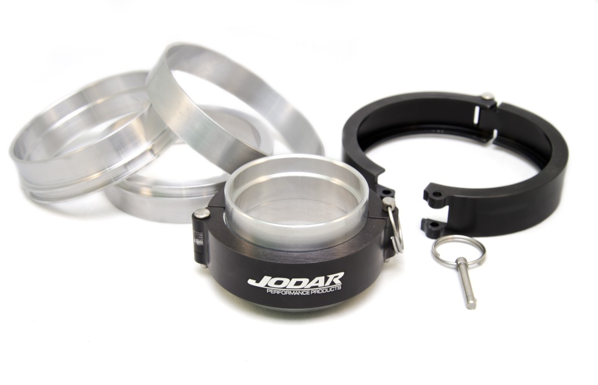
Per RPS’s John Kerr, “V-band connections on a solidly-mounted piece like an intercooler are great, since it’s not an area where you’ll be disconnecting it every pass down the track. The sealing capability of the V-band over silicone is greater as well. Our V-band connections have a male and female end that interlock, with an O-ring behind that which adds more sealing capability. These have been tested to 175 PSI.”
You can’t just use a V-band for every connection, however – tire shake and system maintenance must also be taken into account, and for that reason most systems have at least one flexible connection to minimize the risk of tubing sections separating from one another during vehicle operation. That being said, if possible it’s always a good idea to use a positive-seal connection like a V-band for any connection inside the cabin of the vehicle, as nobody wants to lose an eardrum or back window when an intercooler tube pops off under high-boost conditions. Use of positive-seal connections is critical in these important locations.
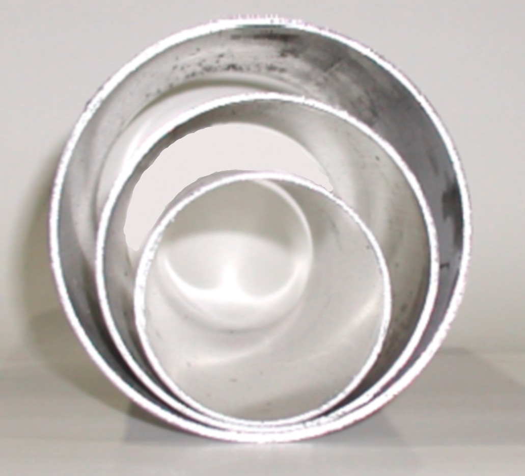
A simple display of the differences between 3-, 4-, and 5-inch tubing. The larger diameter of the tube, the greater volume of air can move without frictional losses against the walls of the tube.
“Most guys will use at least one silicone connection somewhere in the system. We’ve also come out with a product called the dual-seal connector that is an aluminum clamping system that uses very thick o-rings to permit up to 30 degrees of deflection, and many guys are using those in place of silicone. Some of that comes down to budget more than anything – silicone connections can be had for as little as $10, versus $100-plus for a dual-seal connector or $400 for a Wiggins-style clamshell clamp,” says Kerr.

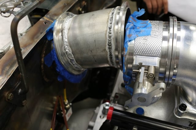
Left to Right - We're using V-band connections in every position that we can for a positive seal. Note how massive the 5-inch tubing is in the engine bay and inside the car. Its size is the main issue with packaging, but if planned out properly it will work just fine. The expected performance increase due to the fact that we've got much less tubing in the car before the boost gets to the intercooler and subsequently the manifold should be well worth the expense and effort of running the system this way.
Another concern is safety – the intercooler and attendant water tank should not be placed in an area that will make it difficult to exit the vehicle in the event of an on-track mishap, and you should always be respectful of the tremendous amount of energy “spring loading” an intercooler and its attendant tubing. Nobody wants to be climbing over a massive intercooler when the car’s up against the wall on one side, the fire system has been activated and flames are licking up under the dash, so plan your system to enable a quick exit if necessary. In our application, that won’t be an issue as the intercooler is not in the way of egress from either door of the car. We have seen many instances where the intercooler would force a driver to climb over it should he or she have to go out the passenger side, and that’s not an easy task when your helmet is on and HANS-device tethers are attached. Safety first!
It’s also sobering to consider the forces in play when the system is at full boost. Some quick high school geometry tells us that our 5-inch intake tube has a cross-section of 19.625 square inches, and when our target boost of 30 PSI is flowing through the system, there will be more than 580 pounds of force trying to pull apart every connection. The intercooler is under even greater stress – with an approximate one square foot core, it will have to endure a shocking 4,320 pounds of force trying to rip it in half. That’s like suspending the entire car and the golf cart to tow it complete with pit crew from the end tanks. Obviously, quality and strength are our number one concern, and Chiseled gives us great peace-of-mind in this respect.
Cool Under Pressure
As you can see, there’s a lot more to setting up a proper air-to-water intercooling system than just ordering a few parts. It’s always best to consult with the manufacturer of the parts you plan on using to ensure that they will be adequate for your application. Take care in planning your system, and it will perform as required, with low boost-pressure loss and high performance when the chips are down on the track.
